The Contamination Fallacy: When Physics Mistakes Fractals for Dirt
By James Johan Sebastian Allen — PatternFieldTheory.com
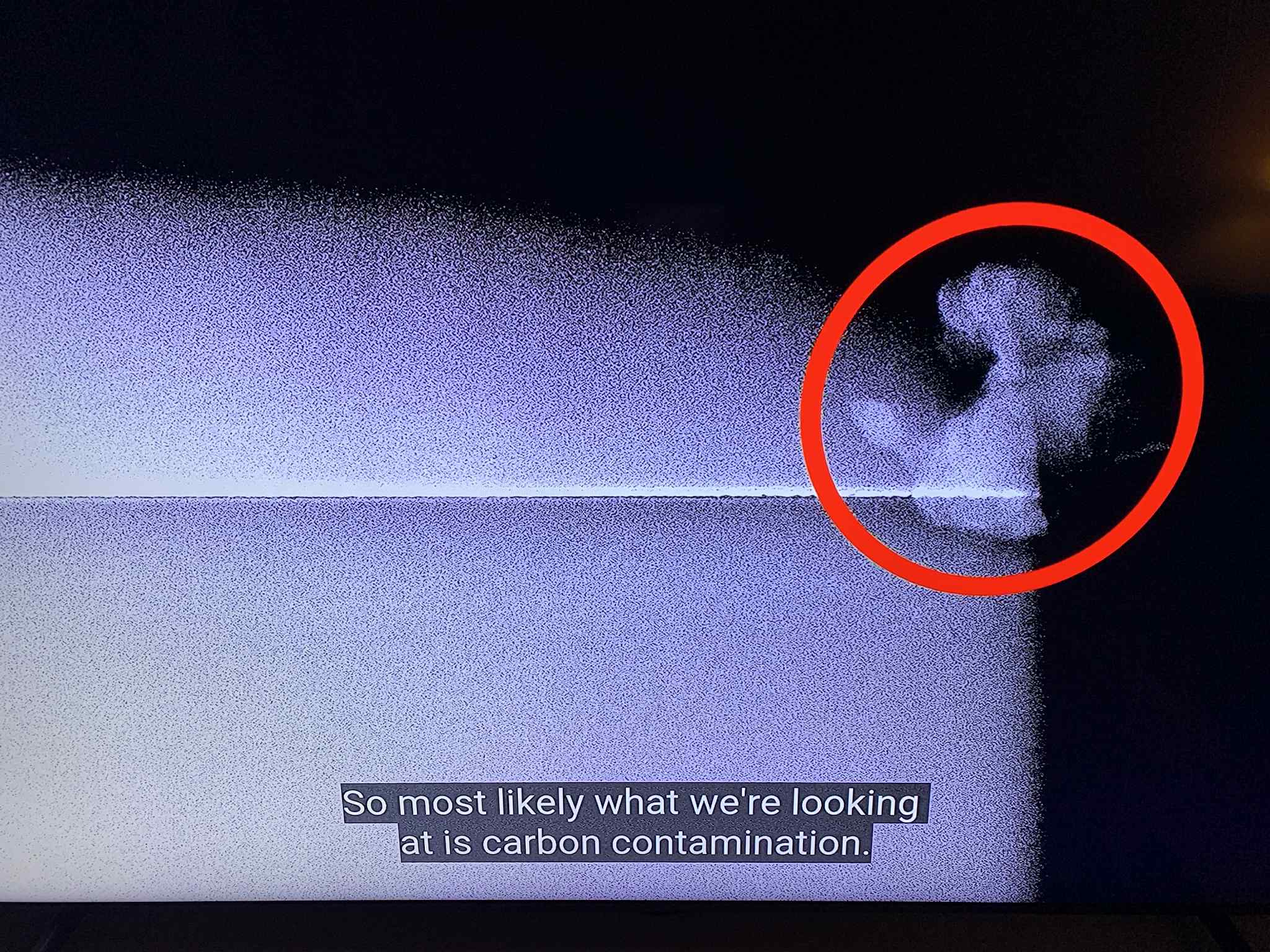
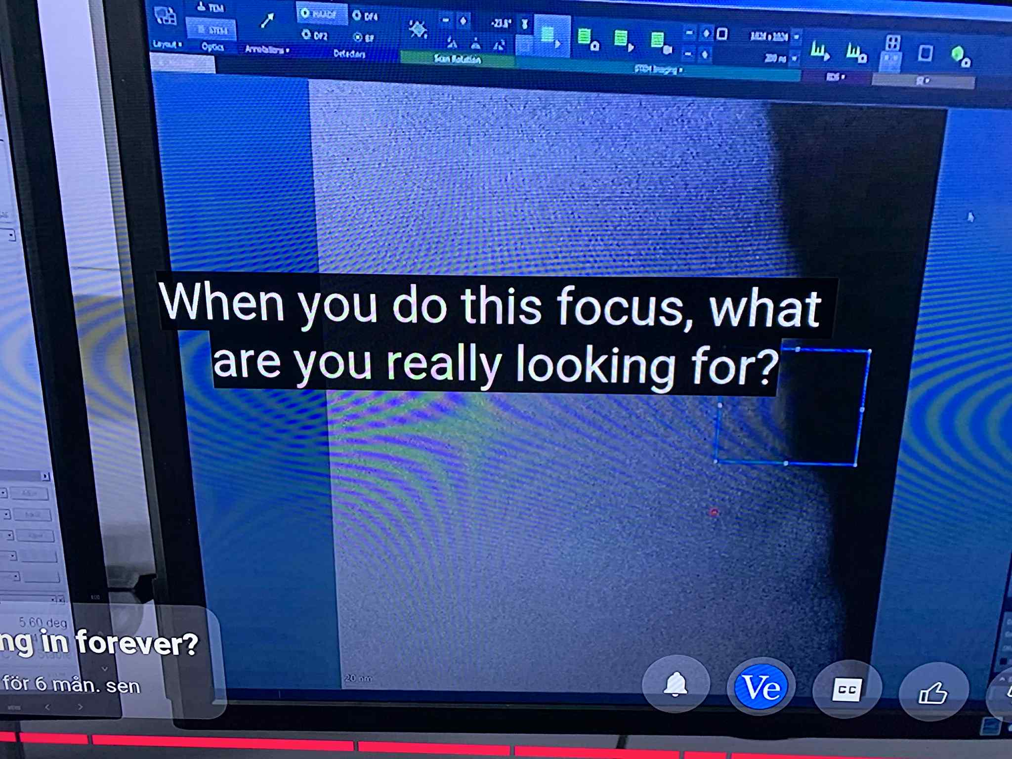
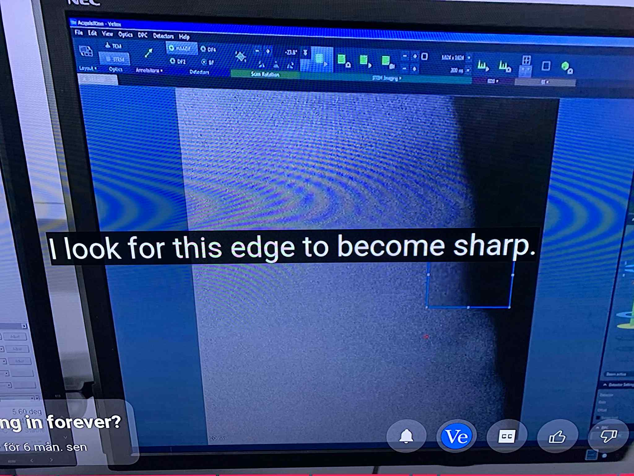
In the control room, the sample is tilted, the beam aligned, the focus tightened. The operator is asked, “When you do this focus, what are you really looking for?” — and the answer comes back without hesitation: “I look for this edge to become sharp. See atoms.” The procedure is clear: remove everything that looks like blur, flatten every halo, erase every irregular patch. When something resists neatness — a branching cloud, a fuzzy bloom, a patch that will not discretize into identical dots — the reflex is immediate: contamination.
Pattern Field Theory (PFT) disagrees. The objects dismissed as “contamination” routinely exhibit hallmark features of a fractal cascade — branching growth, self-similarity, anisotropic envelopes and coherent, non-random textures. Even when the material is indeed carbon, the form it takes under the beam carries information: the Pi Matrix is structuring matter as it deposits, reorganizes and migrates. The “contamination” isn’t meaningless dirt; it’s the substrate’s behavior made visible.
“That’s Most Likely Carbon…”
In the sequence you’ve seen, the operator identifies a textured, cloud-like patch as carbon contamination. The label ends the inquiry. But look at the shape. It branches. It clumps with a preferred scale. It shows gradients of intensity that repeat across smaller regions. That is not random noise; it is structured growth. In PFT, such patterns are not treated as errors to be cleaned away, but as data from the underlying resonance field — the Pi Matrix — shaping how matter organizes on surfaces during imaging and focusing.
IMG_9F4B57C2-B481-4ACD-98EF-0E2513B3899B.jpeg).
Resonance Alignment, Not Just Optics
Before the “wow” moment, you hear: “If we had some random direction, then everything would be just blurred. So that’s why we have to do some tilting in the end.” To mainstream ears, that’s geometric housekeeping. In PFT, it’s something deeper: resonance alignment. The tilt is not only to match the crystal axes to the beam; it’s to synchronize the microscope with the coherence channels of the Pi Matrix. Absent that alignment, the camera integrates across many out-of-phase microstates, and the result is the familiar haze — which is precisely the fractal cascade on camera.
IMG_D753E4AF-9E77-47D4-91F2-F81433769DB1.jpeg).
The Sharpness Fallacy → Zeno Frame
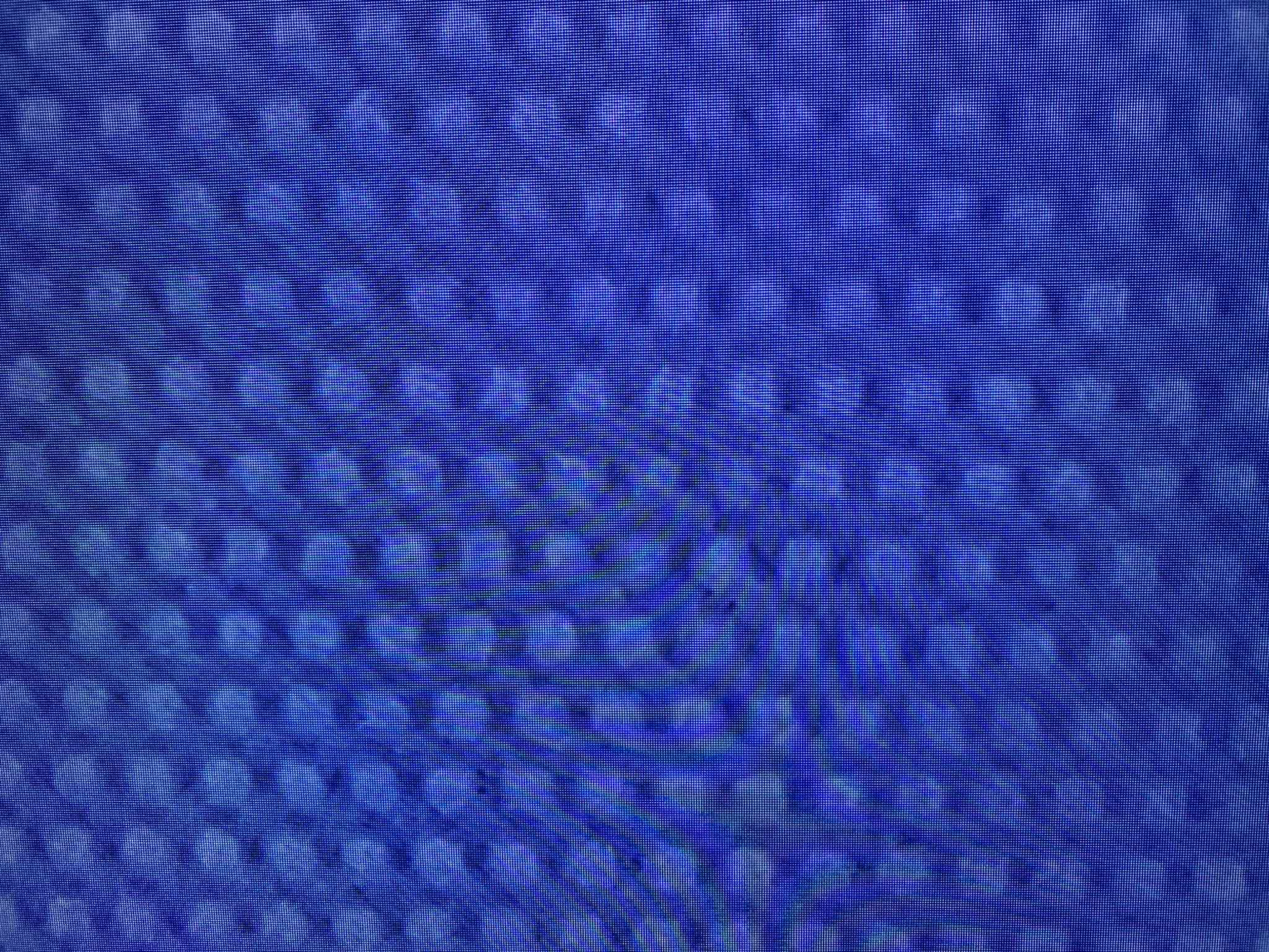
The operator’s answer — “I look for this edge to become sharp. See atoms.” — reveals the underlying philosophy: sharpness equals truth. PFT calls this the Sharpness Fallacy. What the optics accomplish is a forced freeze of motion, collapsing a continuous fractal transition into a still snapshot — a Zeno Frame. The “atoms” that pop into view are not the bottom of reality; they’re a frozen set of resonance nodes in a living field. Crucially, even at 0.13 nm, the image retains structured halos. Those halos are the part the instrument could not freeze — the update-rate mismatch between the Pi Matrix and the camera.
IMG_B1E5244D-E7B9-492C-BC93-4CBA5D298710.jpeg).
Why “Contamination” Looks Fractal
In a living field, added material (even unwanted hydrocarbons) doesn’t randomly smear; it tends to cohere along existing resonance gradients. Under the beam, local heating, charging, diffusion and field-driven migration amplify this effect. The result is fractal accretion: branching, self-similar textures tracking coherence channels in the Logical Layer (the ghostlike substrate that PFT identifies beneath the visible lattice). Call the element carbon if you like — the geometry is the message.
A Minimal Model for the Halo
PFT treats the haze as signal. Let f(ℓ) be the effective iteration rate of resonance at scale ℓ; let fs be the sampling/update rate. If f(ℓ) ≫ fs, under-sampling produces a structured halo (a fractal average of many microstates). A useful phenomenology:
Fractal refresh: f(ℓ) = f₀ · (ℓ₀/ℓ)^α (α ≈ D − 1, linking to fractal dimension D)
Halo thickness: b ≈ (v_eff / f_s) · ( f(ℓ) / f_s )^γ (0 ≤ γ ≤ 1, empirically fitted)
Here veff is an effective phase-velocity in the image plane. This simple scaling explains why halos persist after “full” correction: the field iterates faster than the camera freezes — hence a partial Zeno Frame. The so-called contamination is the same logic expressed as material accretion along coherence channels.
Why This Matters (and How to Test It)
- Power spectra: Lattice peaks plus a 1/fγ background indicate order riding a fractal cascade.
- Box-counting: Estimating D on “contamination” patches should return D in the 1.2–1.7 range typical of accretion fractals.
- Integration-time sweep: Shorter integration → thinner halo; longer integration → thicker, more self-similar halo.
- Tilt sweep: Small tilt changes that increase/decrease resonance alignment should modulate both halo and “contamination” geometry.
Reframing the Carbon Clip
The transcript line — “We see strontium, titanium, oxygen, we see carbon — that’s contamination.” — reveals a habit of mind: if it isn’t part of the target lattice, it’s meaningless. PFT flips this: if it is patterned, it’s meaningful. The fact that carbon arrives as a fractal bloom rather than undifferentiated fog indicates the Logical Layer is guiding deposition in real time. In other words, the “contamination” is a live probe of the substrate.
Conclusion: Stop Cleaning Away the Evidence
The Contamination Fallacy is the habit of scrubbing the most informative part of the image — the dynamic, structured, scale-repeating growth — because it offends our fetish for sharpness. Pattern Field Theory asks a different question: What is the substrate telling us through the way matter actually behaves under observation? When “contamination” blooms along coherence channels, when halos persist after correction, when ghost layers appear beneath the lattice, the Pi Matrix is speaking. The task is not to sterilize the picture, but to learn to read it.